p.862025 Joint Appendices UWith.Cont.Insul Calculated U-factor of the construction assembly with a specific R-value of
p.86continuous insulation. UCol.A A U-factor selected from column A. RCont.Insul The R-value of continuous insulation.
p.86If insulation layers are added that are interrupted by furring strips, then the effective R-values from Table 4. 3.13 shall be used in Equation 4-1.
p.86JA4.1.2.3 Accounting for Unusual Construction Layers
p.86The assumptions that are the basis of the U-factors published in this appendix are documented in the paragraphs following each table. California Energy Commission approved software used for prescriptive or performance calculations may be used to make adjustments to these assumptions based on data entered by the software user. Adjustments may only be made, however, when the total R-value of the proposed construction is at least an R-2 greater than the documented assumption. Each table includes the assumptions used to determine the U-factors.
p.86Equation 4-2 shall be used to make these adjustments.
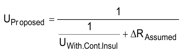
Equation text: 1 U = Pr oposed 1 + ∆RAssumed UWith.Cont.Insul
Needs visual review
p.86Where: UProposed Calculated U-factor of the proposed construction assembly. UWith.Cont.Insul The U-factor adjusted for continuous insulation using Equation 4-1. RAssumed The difference in R-value between what was assumed in the table and the
p.86proposed construction for a continuous layer.
p.86There are limits, however, on the types of adjustments that can be made.
p.86(a) The difference in resistance shall be at least R-2. When calculating the difference
p.86in R-value, no changes in assumptions shall be made to the framing/insulation layer; the proposed construction shall assume the same values as the table.
p.86(b) The thermal resistance of air layers shall be taken from the 2009 ASHRAE
p.86Handbook of Fundamentals, for a mean temperature of 50°F, a temperature difference of 20 °F and an effective emittance of 0.82.
p.86(c) R-values for air layers for roof and ceiling assemblies shall be based on heat flow
p.86up. R-values for air layers for floor assemblies shall be based on heat flow down. R-values for other assemblies shall be based on horizontal heat flow. Air layers must be sealed on edges to prevent air layer mixing with ambient air.
p.86(d) One additional air gap may be credited, but not air gaps that are within the framing
p.86insulation cavity layer; these are already accounted for in the published data. Air gaps of less than 0.5 inch thickness shall be considered to have an R-value of zero. An example of an acceptable additional air gap would be the space between a brick veneer and the sheathing on the framed wall.
p.86Appendix JA4 – U-factor, C-factor, and Thermal Mass Data