p.922025 Joint Appendices
p.942025 Joint Appendices
p.962025 Joint Appendices Appendix JA15 Table 4.2.2 – Continued U-factors of Wood Framed Rafter Roofs – 24 in. OC Rafter Spacing
p.982025 Joint Appendices Appendix JA17 at the ceiling, between the drywall and the framing. The framing percentage is assumed to be 10 percent for 16 inch OC and 7 percent for 24 inch. OC. The thickness of framing members is assumed to be the actual size of 3.50, 5.50, 7.25, 9.25, and 11.25 inches for 2x4, 2x6, 2x8, 2x10, and 2x12 nominal sizes. High-density batt insulation is assumed to be 8.5 inch thick for R-30 and 10.5 inch thick for R-38. The R-value of sprayed foam and cellulose insulation is assumed to be R-3.6 per inch.
p.1002025 Joint Appendices Appendix JA19
p.93common construction for low-rise residential buildings and for Type V nonresidential buildings. While the sketch shows a truss system with a flat ceiling, the data in this table may be used for scissor trusses and other non-flat trusses. If the bottom chord is not flat, then the slope should not exceed 4:12 for nonadhesive binder blown insulation. This table may also be used with composite trusses that have a wood top and bottom chord and metal struts connecting them.
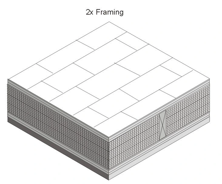
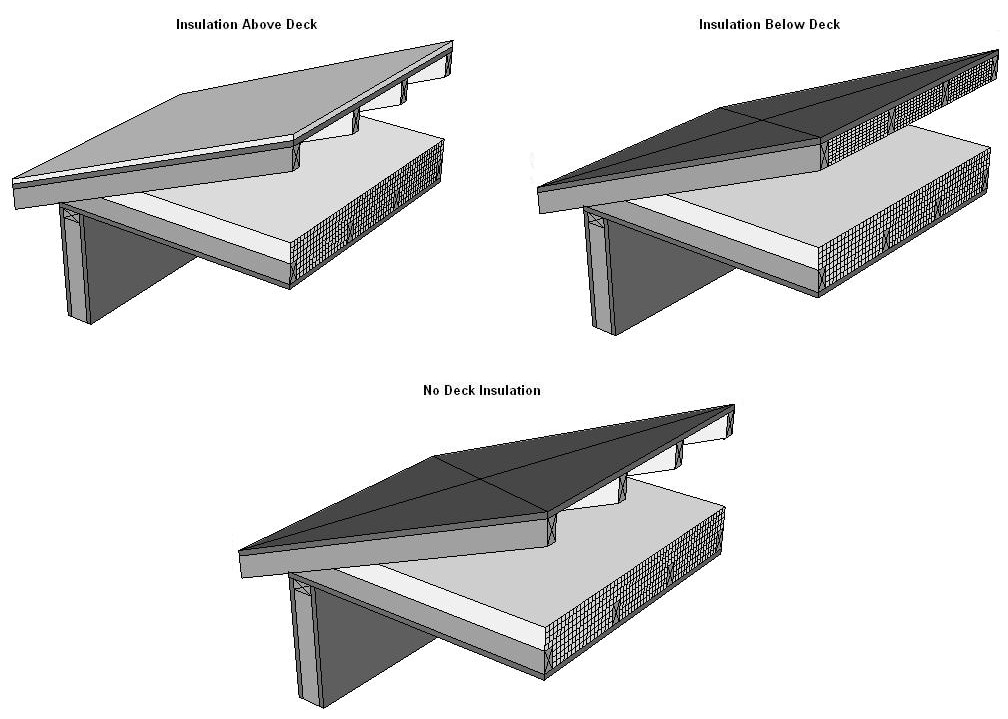
p.97Appendix JA16 buildings. The rafters may be either flat or in a sloped application. Insulation is typically installed between the rafters. With this construction, the insulation is in contact with the ceiling and there is typically a one-inch air gap above the insulation so that moisture can be vented. Whether there is an air space above the insulation depends on local climate conditions and may not be required in some building permit jurisdictions. Filling the entire cavity of framed rafter assemblies with loose-fill mineral fiber and wool, cellulose, or ocSPF requires prior approval by the local building official.
p.101Appendix JA20 Data from Column A will be used in most cases, since it is quite unusual to add continuous insulation to a panel that is basically all insulation anyway. If insulation is added, however, then the U-factor is selected from one of the other columns. If the tables are used manually, then the installed insulation shall have a thermal resistance at least as great as the column selected. When the table is used with CEC approved compliance software, then the R-value of any amount of continuous insulation may be accounted for along with the thermal resistance of special construction layers may be accounted for using Equation 4-1 and Equation 4-2.
p.103Appendix JA22 For the majority of cases, values will be selected from column A of this table. Column A applies for the common situation where either batt or blown insulation is placed directly over the ceiling. Builders or designers may increase thermal performance by adding a continuous insulation layer at the ceiling. The continuous insulation is typically a rigid polystyrene or polyisocyurnate foam insulation. Continuous insulation does not include the blown or batt insulation that is over the bottom chord of the truss (this is already accounted for in the first column data).
p.100In climate zones 1 and 16 the insulating R-value of continuous insulation materials installed above the roof waterproof membrane shall be multiplied times 0.8 before choosing the table column for determining assembly U-factor.
p.92JA4.2 Roofs and Ceilings
p.102Rated R-value of Continuous Insulation1
p.94This table shall not be used for cases where insulation is located at the roof of the attic. There are several situations in which this may be done. For example, in a sealed attic, foamed plastic may be sprayed onto the top chord of the trusses and onto the bottom of the upper structural deck (roof). The foam expands and cures with the intent of providing an airtight barrier and continuous insulation. Another case is where a plastic membrane or netting is installed above the ceiling (hanging below the roof deck) either in a ventilated or sealed (not ventilated) attic, and then either batt or blown insulation is installed over the netting. Since there are a number of issues related to these insulation techniques, special CEC approval is required.
p.95Rated R-value of Continuous Insulation5
p.99Rated R-value of Continuous Insulation 4,5
p.96Rated R-value of Continuous Insulation5
| Nominal Framing Size | Cavity Insulation R-Value: | R-0 | R-2 | R-4 | R-6 | R-7 | R-8 | R-10 | R-14 |
|---|---|---|---|---|---|---|---|---|---|
| Any | None | 0.328 | 0.198 | 0.142 | 0.111 | 0.100 | 0.091 | 0.077 | 0.059 |
| 2 x 4 | R-11 | 0.126 | 0.101 | 0.084 | 0.072 | 0.067 | 0.063 | 0.056 | 0.046 |
| (3.65 in.) | R-13 | 0.121 | 0.097 | 0.082 | 0.070 | 0.066 | 0.061 | 0.055 | 0.045 |
| (3.65 in.) | R-19 | 0.071 | 0.062 | 0.055 | 0.050 | 0.047 | 0.045 | 0.042 | 0.036 |
| (3.65 in.) | R-21 | 0.063 | 0.056 | 0.050 | 0046 | 0.044 | 0.042 | 0.039 | 0.033 |
| (3.65 in.) | R-22 | 0.059 | 0.053 | 0.048 | 0.044 | 0.042 | 0.040 | 0.037 | 0.032 |
| (3.65 in.) | R-25 | 0.051 | 0.046 | 0.042 | 0.039 | 0.038 | 0.036 | 0.034 | 0.030 |
| (3.65 in.) | R-30 | 0.041 | 0.038 | 0.035 | 0.033 | 0.032 | 0.031 | 0.029 | 0.026 |
| (3.65 in.) | R-38 | 0.031 | 0.029 | 0.028 | 0.026 | 0.025 | 0.025 | 0.024 | 0.022 |
| (3.65 in.) | R-44 | 0.027 | 0.026 | 0.024 | 0.023 | 0.023 | 0.022 | 0.021 | 0.020 |
| (3.65 in.) | R-49 | 0.024 | 0.023 | 0.022 | 0.021 | 0.021 | 0.020 | 0.019 | 0.018 |
| (3.65 in.) | R-60 | 0.019 | 0.018 | 0.018 | 0.017 | 0.017 | 0.016 | 0.016 | 0.015 |
| R-value of Cavity Insulatio n | Nominal Framing Size | None | R-2 | R-4 | R-6 | R-7 | R-8 | R-10 | R-14 | R-17 | R-20 | R-23 |
|---|---|---|---|---|---|---|---|---|---|---|---|---|
| None | Any | 0.297 | 0.186 | 0.136 | 0.107 | 0.096 | 0.088 | 0.075 | 0.058 | 0.049 | 0.043 | 0.038 |
| R-112 | 2x4 | 0.084 | 0.072 | 0.063 | 0.056 | 0.053 | 0.050 | 0.046 | 0.039 | 0.035 | 0.031 | 0.029 |
| R-132 | 2x4 | 0.075 | 0.065 | 0.058 | 0.052 | 0.049 | 0.047 | 0.043 | 0.037 | 0.033 | 0.030 | 0.028 |
| R-152 | 2x4 | 0.068 | 0.060 | 0.053 | 0.048 | 0.046 | 0.044 | 0.040 | 0.035 | 0.032 | 0.029 | 0.027 |
| R-192 | 2x4 | 0.075 | 0.065 | 0.058 | 0.052 | 0.049 | 0.047 | 0.043 | 0.037 | 0.033 | 0.030 | 0.028 |
| R-192,3 | 2x4 | 0.062 | 0.055 | 0.050 | 0.045 | 0.043 | 0.041 | 0.038 | 0.033 | 0.030 | 0.028 | 0.026 |
| R-11 | 2x6 | 0.076 | 0.066 | 0.058 | 0.052 | 0.050 | 0.047 | 0.043 | 0.037 | 0.033 | 0.030 | 0.028 |
| R-13 | 2x6 | 0.069 | 0.061 | 0.054 | 0.049 | 0.047 | 0.044 | 0.041 | 0.035 | 0.032 | 0.029 | 0.027 |
| R-15 | 2x6 | 0.062 | 0.055 | 0.050 | 0.045 | 0.043 | 0.041 | 0.038 | 0.033 | 0.030 | 0.028 | 0.026 |
| R-192 | 2x6 | 0.056 | 0.050 | 0.046 | 0.042 | 0.040 | 0.039 | 0.036 | 0.031 | 0.029 | 0.026 | 0.024 |
| R-212 | 2x6 | 0.052 | 0.047 | 0.043 | 0.040 | 0.038 | 0.037 | 0.034 | 0.030 | 0.028 | 0.025 | 0.024 |
| R-192 | 2x8 | 0.051 | 0.046 | 0.042 | 0.039 | 0.038 | 0.036 | 0.034 | 0.030 | 0.027 | 0.025 | 0.023 |
| R-21 | 2x8 | 0.048 | 0.044 | 0.040 | 0.037 | 0.036 | 0.035 | 0.032 | 0.029 | 0.026 | 0.024 | 0.023 |
| R-22 | 2x10 | 0.044 | 0.040 | 0.037 | 0.035 | 0.034 | 0.033 | 0.031 | 0.027 | 0.025 | 0.023 | 0.022 |
| R-25 | 2x10 | 0.041 | 0.038 | 0.035 | 0.033 | 0.032 | 0.031 | 0.029 | 0.026 | 0.024 | 0.023 | 0.021 |
| R-304 | 2x10 | 0.036 | 0.034 | 0.031 | 0.030 | 0.029 | 0.028 | 0.026 | 0.024 | 0.022 | 0.021 | 0.020 |
| R-30 | 2x12 | 0.035 | 0.033 | 0.031 | 0.029 | 0.028 | 0.027 | 0.026 | 0.023 | 0.022 | 0.021 | 0.019 |
| R-384 | 2x12 | 0.029 | 0.027 | 0.026 | 0.025 | 0.024 | 0.024 | 0.022 | 0.021 | 0.019 | 0.018 | 0.017 |
| R-384 | 2x14 | 0.028 | 0.027 | 0.025 | 0.024 | 0.023 | 0.023 | 0.022 | 0.020 | 0.019 | 0.018 | 0.017 |
| R-value of Cavity Insulatio n | Nominal Framing Size | None | R-2 | R-4 | R-6 | R-7 | R-8 | R-10 | R-14 | R-17 | R-20 | R-23 |
| None | Any | 0.237 | 0.161 | 0.122 | 0.098 | 0.089 | 0.082 | 0.070 | 0.055 | 0.047 | 0.041 | 0.037 |
| R-112 | 2x4 | 0.081 | 0.070 | 0.061 | 0.055 | 0.052 | 0.049 | 0.045 | 0.038 | 0.034 | 0.031 | 0.028 |
| R-132 | 2x4 | 0.072 | 0.063 | 0.056 | 0.050 | 0.048 | 0.046 | 0.042 | 0.036 | 0.032 | 0.030 | 0.027 |
| R-152 | 2x4 | 0.065 | 0.058 | 0.052 | 0.047 | 0.045 | 0.043 | 0.039 | 0.034 | 0.031 | 0.028 | 0.026 |
| R-192 | 2x4 | 0.072 | 0.063 | 0.056 | 0.050 | 0.048 | 0.046 | 0.042 | 0.036 | 0.032 | 0.030 | 0.027 |
| R-192,3 | 2x4 | 0.059 | 0.053 | 0.048 | 0.044 | 0.042 | 0.040 | 0.037 | 0.032 | 0.029 | 0.027 | 0.025 |
| R-11 | 2x6 | 0.075 | 0.065 | 0.058 | 0.052 | 0.049 | 0.047 | 0.043 | 0.037 | 0.033 | 0.030 | 0.028 |
| R-13 | 2x6 | 0.067 | 0.059 | 0.053 | 0.048 | 0.046 | 0.044 | 0.040 | 0.035 | 0.031 | 0.029 | 0.026 |
| R-152 | 2x6 | 0.060 | 0.054 | 0.048 | 0.044 | 0.042 | 0.041 | 0.038 | 0.033 | 0.030 | 0.027 | 0.025 |
| R-192 | 2x6 | 0.054 | 0.049 | 0.044 | 0.041 | 0.039 | 0.038 | 0.035 | 0.031 | 0.028 | 0.026 | 0.024 |
| R-212 | 2x6 | 0.049 | 0.045 | 0.041 | 0.038 | 0.036 | 0.035 | 0.033 | 0.029 | 0.027 | 0.025 | 0.023 |
| R-192 | 2x8 | 0.049 | 0.045 | 0.041 | 0.038 | 0.036 | 0.035 | 0.033 | 0.029 | 0.027 | 0.025 | 0.023 |
| R-21 | 2x8 | 0.046 | 0.042 | 0.039 | 0.036 | 0.035 | 0.034 | 0.032 | 0.028 | 0.026 | 0.024 | 0.022 |
| R-22 | 2x10 | 0.043 | 0.040 | 0.037 | 0.034 | 0.033 | 0.032 | 0.030 | 0.027 | 0.025 | 0.023 | 0.022 |
| R-25 | 2x10 | 0.039 | 0.036 | 0.034 | 0.032 | 0.031 | 0.030 | 0.028 | 0.025 | 0.023 | 0.022 | 0.021 |
| R-304 | 2x10 | 0.034 | 0.032 | 0.030 | 0.028 | 0.027 | 0.027 | 0.025 | 0.023 | 0.022 | 0.020 | 0.019 |
| R-30 | 2x12 | 0.033 | 0.031 | 0.029 | 0.028 | 0.027 | 0.026 | 0.025 | 0.023 | 0.021 | 0.020 | 0.019 |
| R-38 4 | 2x12 | 0.028 | 0.027 | 0.025 | 0.024 | 0.023 | 0.023 | 0.022 | 0.020 | 0.019 | 0.018 | 0.017 |
| R-384 | 2x14 | 0.027 | 0.026 | 0.024 | 0.023 | 0.023 | 0.022 | 0.021 | 0.020 | 0.019 | 0.018 | 0.017 |
| Wood Framing Connection Type (spline) | Insulation Core R-value1 | Typical Panel Thickness | None | R-2 | R-4 | R-5 | R-7 | R-8 |
|---|---|---|---|---|---|---|---|---|
| OSB | R-22 | 6.5 in | 0.041 | 0.038 | 0.035 | 0.034 | 0.032 | 0.031 |
| Single 2x | R-22 | 6.5 in | 0.044 | 0.040 | 0.037 | 0.036 | 0.033 | 0.032 |
| Double 2x | R-22 | 6.5 in | 0.046 | 0.042 | 0.038 | 0.037 | 0.034 | 0.033 |
| I-joist | R-22 | 6.5 in | 0.043 | 0.039 | 0.036 | 0.035 | 0.033 | 0.032 |
| OSB | R-28 | 8.25 in | 0.033 | 0.031 | 0.029 | 0.028 | 0.027 | 0.026 |
| Single 2x | R-28 | 8.25 in | 0.034 | 0.032 | 0.030 | 0.029 | 0.027 | 0.027 |
| Double 2x | R-28 | 8.25 in | 0.037 | 0.034 | 0.031 | 0.030 | 0.028 | 0.028 |
| I-joist | R-28 | 8.25 in | 0.033 | 0.310 | 0.029 | 0.028 | 0.027 | 0.026 |
| OSB | R-332 | 6.5 in | 0.030 | 0.027 | 0.026 | 0.025 | 0.024 | 0.023 |
| Single 2x | R-332 | 6.5 in | 0.031 | 0.029 | 0.027 | 0.026 | 0.025 | 0.024 |
| Double 2x | R-332 | 6.5 in | 0.034 | 0.031 | 0.029 | 0.028 | 0.026 | 0.025 |
| I-joist | R-332 | 6.5 in | 0.031 | 0.028 | 0.027 | 0.026 | 0.025 | 0.024 |
| OSB | R-36 | 10.25 in | 0.026 | 0.025 | 0.024 | 0.023 | 0.022 | 0.022 |
| Single 2x | R-36 | 10.25 in | 0.028 | 0.026 | 0.025 | 0.024 | 0.023 | 0.022 |
| Double 2x | R-36 | 10.25 in | 0.029 | 0.028 | 0.026 | 0.025 | 0.024 | 0.023 |
| I-joist | R-36 | 10.25 in | 0.027 | 0.025 | 0.024 | 0.023 | 0.022 | 0.022 |
| OSB | R-44 | 12.25 in | 0.021 | 0.020 | 0.019 | 0.019 | 0.018 | 0.018 |
| Single 2x | R-44 | 12.25 in | 0.023 | 0.022 | 0.021 | 0.021 | 0.020 | 0.019 |
| Double 2x | R-44 | 12.25 in | 0.025 | 0.023 | 0.022 | 0.022 | 0.021 | 0.020 |
| I-joist | R-44 | 12.25 in | 0.022 | 0.021 | 0.020 | 0.020 | 0.019 | 0.019 |
| OSB | R-553 | 10.25 in | 0.017 | 0.016 | 0.016 | 0.016 | 0.016 | 0.016 |
| Single 2x | R-553 | 10.25 in | 0.019 | 0.018 | 0.018 | 0.018 | 0.017 | 0.016 |
| Double 2x | R-553 | 10.25 in | 0.021 | 0.020 | 0.019 | 0.019 | 0.018 | 0.017 |
| I-joist | R-553 | 10.25 in | 0.018 | 0.017 | 0.017 | 0.017 | 0.016 | 0.016 |
| Steel Framing | R-14 | 48 in | 0.075 | 0.065 | 0.058 | 0.055 | 0.049 | 0.047 |
| Steel Framing | R-22 | 48 in | 0.057 | 0.051 | 0.046 | 0.044 | 0.041 | 0.039 |
| Steel Framing | R-28 | 48 in | 0.047 | 0.043 | 0.040 | 0.039 | 0.035 | 0.034 |
| Steel Framing | R-36 | 48 in | 0.043 | 0.040 | 0.037 | 0.036 | 0.033 | 0.032 |
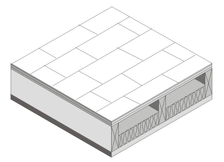
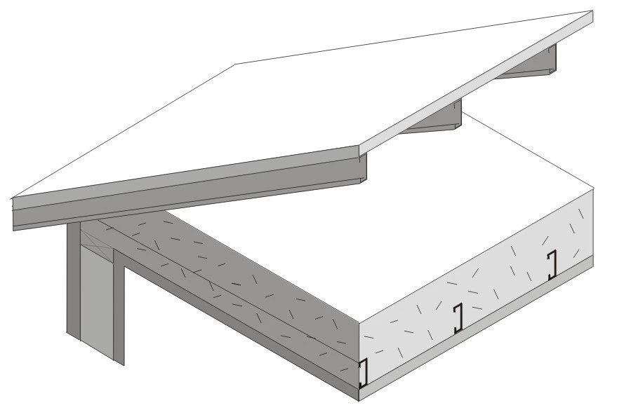
p.100Structural insulated panels (SIPs) consist of a rigid insulation core, securely bonded between two structural facings, to form a structural sandwich panel. SIPs are considered a non-framed assembly usually with little or no structural framing that penetrates the insulation layer, resulting in less thermal bridging across the insulation when compared to a conventional framed assembly.
p.92Rated R-Value of Continuous Insulation1
| R-value of Attic Insulation | None | R-2 | R-4 | R-6 | R-7 | R-8 | R-10 | R-14 |
|---|---|---|---|---|---|---|---|---|
| None | 0.300 | 0.187 | 0.136 | 0.107 | 0.097 | 0.088 | 0.075 | 0.058 |
| R-11 | 0.079 | 0.068 | 0.060 | 0.053 | 0.051 | 0.048 | 0.044 | 0.037 |
| R-13 | 0.071 | 0.062 | 0.055 | 0.050 | 0.047 | 0.045 | 0.041 | 0.036 |
| R-19 | 0.049 | 0.045 | 0.041 | 0.038 | 0.037 | 0.035 | 0.033 | 0.029 |
| R-21 | 0.042 | 0.039 | 0.036 | 0.034 | 0.032 | 0.031 | 0.030 | 0.026 |
| R-22 | 0.043 | 0.039 | 0.037 | 0.034 | 0.033 | 0.032 | 0.030 | 0.027 |
| R-25 | 0.038 | 0.035 | 0.033 | 0.031 | 0.030 | 0.029 | 0.028 | 0.025 |
| R-30 | 0.032 | 0.030 | 0.028 | 0.027 | 0.026 | 0.025 | 0.024 | 0.022 |
| R-38 | 0.026 | 0.024 | 0.023 | 0.022 | 0.022 | 0.021 | 0.020 | 0.019 |
| R-44 | 0.021 | 0.020 | 0.019 | 0.019 | 0.018 | 0.018 | 0.017 | 0.016 |
| R-49 | 0.020 | 0.019 | 0.019 | 0.018 | 0.018 | 0.017 | 0.017 | 0.016 |
| R-60 | 0.017 | 0.016 | 0.016 | 0.015 | 0.015 | 0.015 | 0.014 | 0.013 |
p.96Notes:
p.93For the majority of cases, values will be selected from column A of this table. Column A shall be used for the common situation where either batt or blown insulation is placed directly over the ceiling (and tapered at the edges). Builders or designers may increase thermal performance by adding a continuous insulation layer at the ceiling. The continuous insulation is typically a rigid polystyrene or polyisocyanurate foam insulation. Continuous insulation does not include the blown or batt insulation that is over the bottom chord of the truss (this is already accounted for in the U-factors published in Column A).
p.97For the majority of cases, U-factors will be selected from Column A of this table; this case covers insulation placed only in the cavity. When continuous insulation is installed either at the ceiling or at the roof, then U-factors from other columns may be selected. The continuous insulation is typically a rigid polystyrene or polyisocyanurate foam insulation, but can also include mineral wool or other suitable materials.
p.103When this table is used manually, the R-value of continuous insulation shall be equal to or greater than the R-value published in the continuous insulation columns. No interpolation is permitted when data from the table is used manually. CEC approved software, however, may determine the U-factor for any amount of continuous insulation and for unusual construction layers using Equation 4-1 and Equation 4-2.
p.100This table gives U-factors for structurally insulated panels used in ceiling and roof constructions. Data is provided for three variations of this system. The system labeled “Wood Framing” uses wood spacers to separate the plywood or OSB boards and provide a means to connect the panels with mechanical fasteners. The system labeled “Steel Framing” uses steel framing members and mechanical fasteners at the joints. The system labeled “OSB Spline” uses splines to connect the panels so that framing members do not penetrate the insulation.
p.101Assumptions: The wood framing and OSB spline data are calculated using the parallel path method documented in the 2009 ASHRAE Handbook of Fundamentals. Assemblies with metal framing are calculated using the ASHRAE Zone Calculation Method which is also documented in the 2005 ASHRAE Handbook of Fundamentals. These calculations assume an exterior air film of R-0.17, asphalt shingles of R-0.44 (AR02), building paper of R-0.06 (BP01), 7/16 inch of OSB of R-0.69, the rigid insulation of R-3.85 per inch, another layer of 7/16 inch of OSB, 1⁄2 inch gypsum board of R-0.45 (GP01), an R-value of 0.99 per inch is assumed for the wood frame and an interior air film (heat flow up diagonally) of R 0.62. If an additional layer of insulation is used, this may be installed on either the interior or exterior of the SIPS panel assembly.
p.94Assumptions: This data is calculated using the parallel path method documented in the 2009 ASHRAE Handbook of Fundamentals. These calculations assume an exterior air film of R-0.17, asphalt shingles of R-0.44 (AR02), building paper of R-0.06 (BP01), 1⁄2 inch of wood based sheathing (Custom), an attic air space (greater than 3.5 inch) with a R 0.80, the insulation / framing layer, continuous insulation (if any) 1⁄2 inch gypsum board (GP01) of R-0.45, and an interior air film (heat flow up) of R-0.61. Wood 2x4 framing is assumed at the ceiling level. R-13 of attic insulation is assumed between the framing members; above that level, attic insulation is uninterrupted by framing. The framing percentage is assumed to be 10 percent for 16 inch on center and 7 percent for 24 inch on center. 7.25 percent of the attic insulation above the framing members is assumed to be at half depth, due to decreased depth of insulation at the eaves.
| Nominal Framing Size | Cavity Insulation R-Value: | R-0 | R-2 | R-4 | R-6 | R-7 | R-8 | R-10 | R-14 |
|---|---|---|---|---|---|---|---|---|---|
| Any | None | 0.324 | 0.197 | 0.141 | 0.110 | 0.099 | 0.090 | 0.076 | 0.059 |
| 2 x 4 | R-11 | 0.109 | 0.089 | 0.076 | 0.066 | 0.062 | 0.058 | 0.052 | 0.043 |
| (3.65 in.) | R-13 | 0.103 | 0.085 | 0.073 | 0.064 | 0.060 | 0.056 | 0.051 | 0.042 |
| (3.65 in.) | R-19 | 0.065 | 0.058 | 0.052 | 0.047 | 0.045 | 0.043 | 0.039 | 0.034 |
| (3.65 in.) | R-21 | 0.058 | 0.052 | 0.047 | 0.043 | 0.041 | 0.040 | 0.037 | 0.032 |
| (3.65 in.) | R-22 | 0.055 | 0.050 | 0.045 | 0.041 | 0.040 | 0.038 | 0.035 | 0.031 |
| (3.65 in.) | R-25 | 0.047 | 0.043 | 0.040 | 0.037 | 0.035 | 0.034 | 0.032 | 0.028 |
| (3.65 in.) | R-30 | 0.039 | 0.036 | 0.034 | 0.032 | 0.031 | 0.030 | 0.028 | 0.025 |
| (3.65 in.) | R-38 | 0.030 | 0.028 | 0.027 | 0.025 | 0.025 | 0.024 | 0.023 | 0.021 |
| (3.65 in.) | R-44 | 0.026 | 0.025 | 0.024 | 0.022 | 0.022 | 0.022 | 0.021 | 0.019 |
| (3.65 in.) | R-49 | 0.023 | 0.022 | 0.021 | 0.020 | 0.020 | 0.019 | 0.019 | 0.017 |
| (3.65 in.) | R-60 | 0.019 | 0.018 | 0.018 | 0.017 | 0.017 | 0.016 | 0.016 | 0.015 |
| R-value of Attic Insulation | None | R-2 | R-4 | R-6 | R-7 | R-8 | R-10 | R-14 |
|---|---|---|---|---|---|---|---|---|
| None | 0.305 | 0.189 | 0.137 | 0.108 | 0.097 | 0.089 | 0.075 | 0.058 |
| R-11 | 0.076 | 0.066 | 0.058 | 0.052 | 0.050 | 0.047 | 0.043 | 0.037 |
| R-13 | 0.068 | 0.060 | 0.054 | 0.048 | 0.046 | 0.044 | 0.041 | 0.035 |
| R-19 | 0.048 | 0.043 | 0.040 | 0.037 | 0.036 | 0.034 | 0.032 | 0.029 |
| R-21 | 0.043 | 0.040 | 0.037 | 0.034 | 0.033 | 0.032 | 0.030 | 0.027 |
| R-22 | 0.041 | 0.038 | 0.036 | 0.033 | 0.032 | 0.031 | 0.029 | 0.026 |
| R-25 | 0.037 | 0.034 | 0.032 | 0.030 | 0.029 | 0.028 | 0.027 | 0.024 |
| R-30 | 0.031 | 0.029 | 0.028 | 0.026 | 0.025 | 0.025 | 0.024 | 0.022 |
| R-38 | 0.025 | 0.024 | 0.023 | 0.022 | 0.021 | 0.021 | 0.020 | 0.018 |
| R-44 | 0.021 | 0.020 | 0.019 | 0.019 | 0.018 | 0.018 | 0.017 | 0.016 |
| R-49 | 0.019 | 0.019 | 0.018 | 0.017 | 0.017 | 0.017 | 0.016 | 0.015 |
| R-60 | 0.016 | 0.016 | 0.015 | 0.015 | 0.014 | 0.014 | 0.014 | 0.013 |
p.93Figure 4.2.1 – Wood Framed Attic Roofs
p.92Appendix JA4 – U-factor, C-factor, and Thermal Mass Datap.93
p.93Appendix JA4 – U-factor, C-factor, and Thermal Mass Datap.94
p.94Appendix JA4 – U-factor, C-factor, and Thermal Mass Datap.95
p.95Appendix JA4 – U-factor, C-factor, and Thermal Mass Datap.96
p.96Appendix JA4 – U-factor, C-factor, and Thermal Mass Datap.97
p.97Appendix JA4 – U-factor, C-factor, and Thermal Mass Datap.98
p.98Appendix JA4 – U-factor, C-factor, and Thermal Mass Datap.99
p.99Appendix JA4 – U-factor, C-factor, and Thermal Mass Datap.100
p.100Appendix JA4 – U-factor, C-factor, and Thermal Mass Datap.101
p.101Appendix JA4 – U-factor, C-factor, and Thermal Mass Datap.102
p.102Appendix JA4 – U-factor, C-factor, and Thermal Mass Datap.103
p.103Appendix JA4 – U-factor, C-factor, and Thermal Mass Data