p.359RA3.3 Field Verification and Diagnostic Testing of Forced Air System Airflow Rate, Fan Watt Draw, and Determination of Fan Efficacy.
p.359RA3.3 contains procedures for:
p.359(a) Verification of improved system airflow rate (cfm) in ducted split system and packaged
p.359space conditioning systems serving single-family and multifamily residential buildings.
p.359(b) Verification of reduced fan power (Watt) draw achieved through improved air distribution
p.359system design, including more efficient motors and ducts that have less resistance to airflow.
p.359(c) Determination of fan efficacy (Watt/cfm) utilizing simultaneous measurement of system
p.359Watt draw and airflow rate.
p.359RA3.3.1 Instrumentation Specifications
p.359The instrumentation for the diagnostic measurements shall conform to the following specifications:
p.359RA3.3.1.1 Pressure Measurements
p.359All pressure measurements shall be performed with measurement systems (i.e., sensor plus data acquisition system) having an accuracy of ± 1% of pressure reading or ± 0.2 Pa (.0008 inches water) (whichever is greater). All pressure measurements within the duct system shall be made with static pressure probes such as Dwyer A303 or equivalent.
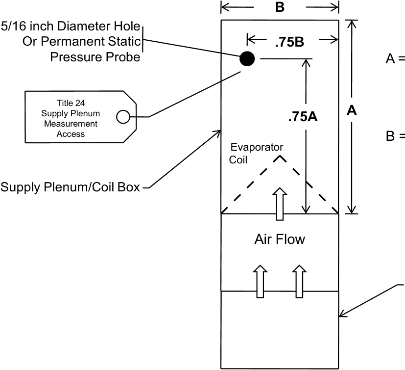
p.359When required for compliance with Standards Section 150.0(m)13A, or when supply plenum pressure measurements are used for plenum pressure matching or flow grid measurements, a 5/16 inch (8 mm) diameter hole for a static pressure probe (HSPP) or a permanently affixed static pressure probe (PSPP) shall be provided as shown in Figure RA3.3-1.
p.359When supply plenum pressure measurements are used for plenum pressure matching or flow grid measurements, the supply plenum pressure measurement shall be taken at the supply plenum measurement access location as shown in Figure RA3.3-1.
p.359The hole location shown in Figure RA3.3-1 can be applied to any one of the four sides of the coil box or supply plenum. The hole location shall be labeled "Title 24 – Supply Plenum Measurement Access" in at least 12-point type.
p.359Systems that cannot conform to the specifications for the hole location shown in Figure RA3.3-1 shall not be required to have holes as described in Figure RA3.3-1; however, if supply plenum pressure measurements are required for compliance, an alternate location that provides access for making an accurate supply plenum pressure measurement shall be used.
p.359Appendix RA3– Residential Field Verification and Diagnostic Test Protocolsp.360
p.3602025 Residential Appendices
Text in this figure
B
A
Air Flow
Evaporator Coil
.75A
.75B
Supply Plenum/Coil Box
Title 24 Supply Plenum
Measurement
Access
5/16 inch Diameter Hole Or Permanent Static
Pressure Probe A = Supply Plenum/Coil Box
p.360dimension parallel to airflow.
p.360B = Supply Plenum/Coil Box
p.360dimension perpendicular to airflow.
p.360Return Plenum/Blower Compartment
p.360Figure RA3.3-1 Hole for the Placement of a Static Pressure Probe (HSPP) or Permanently Installed
p.360Static Pressure Probe (PSPP)