p.3602025 Residential Appendices
Text in this figure
B
A
Air Flow
Evaporator Coil
.75A
.75B
Supply Plenum/Coil Box
Title 24 Supply Plenum
Measurement
Access
5/16 inch Diameter Hole Or Permanent Static
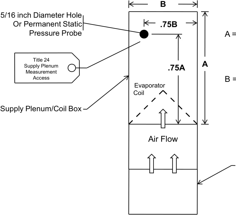
Pressure Probe A = Supply Plenum/Coil Box
p.360dimension parallel to airflow.
p.360B = Supply Plenum/Coil Box
p.360dimension perpendicular to airflow.
p.360Return Plenum/Blower Compartment
p.360Figure RA3.3-1 Hole for the Placement of a Static Pressure Probe (HSPP) or Permanently Installed
p.360Static Pressure Probe (PSPP)
p.360RA3.3.1.2 Airflow Rate Measurements
p.360All measurements of system airflow rates shall be made with an airflow rate measurement apparatus (i.e., sensor plus data acquisition system) having an accuracy of ± 7% of reading or ± 5 cfm whichever is greater.
p.360RA3.3.1.3 Fan Watt Draw Measurements
p.360All measurements of air handler Watt draws shall be made with true power measurement systems (i.e., sensor plus data acquisition system) having an accuracy of ± 2% of reading or ± 10 watts whichever is greater.
p.360RA3.3.2 Apparatus
p.360RA3.3.2.1 System Airflow Rate Measurement Apparatus
p.360Forced air system airflow rate shall be measured using one of the apparatuses listed in Section RA3.3.2. The apparatus shall produce airflow rate measurements that conform to the accuracy requirements specified in Section RA3.3.1.2 for measurements of residential forced air system airflow at system return grilles of single and multiple return duct systems.
p.360The airflow rate measurement apparatus manufacturers shall publish in their product documentation, specifications for how their airflow measurement apparatuses are to be used for
p.360– Residential Field Verification and Diagnostic Test Protocols