Text in this table
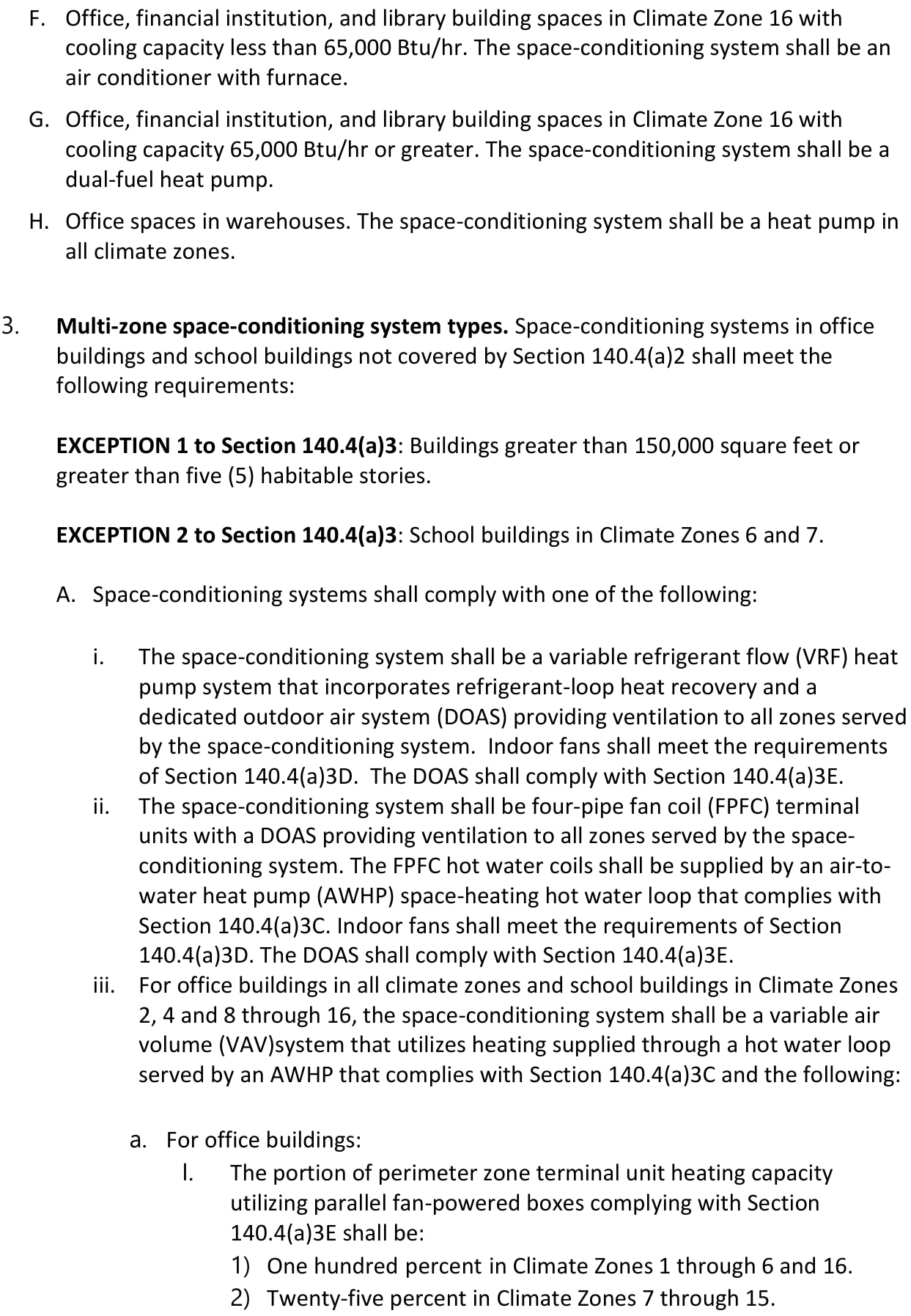
F. Office, financial institution, and library building spaces in Climate Zone 16 with cooling capacity less than 65,000 Btu/hr. The space-conditioning system shall be an air conditioner with furnace. G. Office, financial institution, and library building spaces in Climate Zone 16 with cooling capacity 65,000 Btu/hr or greater. The space-conditioning system shall be a dual-fuel heat pump. H. Office spaces in warehouses. The space-conditioning system shall be a heat pump in all climate zones. 3. Multi-zone space-conditioning system types. Space-conditioning systems in office buildings and school buildings not covered by Section 140.4(a)2 shall meet the following requirements: EXCEPTION 1 to Section 140.4(a)3: Buildings greater than 150,000 square feet or greater than five (5) habitable stories. EXCEPTION 2 to Section 140.4(a)3: School buildings in Climate Zones 6 and 7. A. Space-conditioning systems shall comply with one of the following: i. The space-conditioning system shall be a variable refrigerant flow (VRF) heat pump system that incorporates refrigerant-loop heat recovery and a dedicated outdoor air system (DOAS) providing ventilation to all zones served by the space-conditioning system. Indoor fans shall meet the requirements of Section 140.4(a)3D. The DOAS shall comply with Section 140.4(a)3E. ii. The space-conditioning system shall be four-pipe fan coil (FPFC) terminal units with a DOAS providing ventilation to all zones served by the space- conditioning system. The FPFC hot water coils shall be supplied by an air-to- water heat pump (AWHP) space-heating hot water loop that complies with Section 140.4(a)3C. Indoor fans shall meet the requirements of Section 140.4(a)3D. The DOAS shall comply with Section 140.4(a)3E. iii. For office buildings in all climate zones and school buildings in Climate Zones 2, 4 and 8 through 16, the space-conditioning system shall be a variable air volume (VAV)system that utilizes heating supplied through a hot water loop served by an AWHP that complies with Section 140.4(a)3C and the following: a. For office buildings: I. The portion of perimeter zone terminal unit heating capacity utilizing parallel fan-powered boxes complying with Section 140.4(a)3E shall be: 1) One hundred percent in Climate Zones 1 through 6 and 16. 2) Twenty-five percent in Climate Zones 7 through 15.
| Airflow | Multi-Zone VAV Systems ≤ 5,000 cfm1 | Multi-Zone VAV Systems > 5,000 and ≤ 10,000 cfm1 | Multi-Zone VAV Systems > 10,000 cfm1 | All Other Fan Systems ≤ 5,000 cfm | All Other Fan Systems > 5,000 and ≤ 10,000 cfm | All Other Fan Systems > 10,000 cfm |
|---|---|---|---|---|---|---|
| Supply System Base Allowance for AHU serving spaces ≤ 6 floors away. | 0.395 | 0.453 | 0.413 | 0.232 | 0.256 | 0.236 |
| Supply system base allowance for AHU serving spaces > 6 floors away | 0.508 | 0.548 | 0.501 | 0.349 | 0.356 | 0.325 |
| MERV 13 to MERV 16 Filter upstream of thermal conditioning equipment (two times the clean filter pressure drop)2 | 0.136 | 0.114 | 0.105 | 0.139 | 0.120 | 0.107 |
| MERV 13 to MERV 16 Final filter downstream of thermal conditioning equipment. (two times the clean filter pressure drop)2 | 0.225 | 0.188 | 0.176 | 0.231 | 0.197 | 0.177 |
| Filtration allowance for > MERV 16 or HEPA Filter (two times the clean filter pressure drop) 2 | 0.335 | 0.280 | 0.265 | 0.342 | 0.292 | 0.264 |
| Central Hydronic heating coil allowance | 0.046 | 0.048 | 0.052 | 0.046 | 0.050 | 0.054 |
| Electric heat allowance | 0.046 | 0.038 | 0.035 | 0.046 | 0.040 | 0.036 |
| Gas heat allowance | 0.069 | 0.057 | 0.070 | 0.058 | 0.060 | 0.072 |
| Hydronic/DX cooling coil or heat pump coil (wet) allowance3 | 0.135 | 0.114 | 0.105 | 0.139 | 0.120 | 0.107 |
| Solid or liquid Desiccant system allowance | 0.157 | 0.132 | 0.123 | 0.163 | 0.139 | 0.124 |
| Reheat Coil for Dehumidification Allowance | 0.045 | 0.038 | 0.035 | 0.046 | 0.040 | 0.036 |
| Allowance for Evaporative humidifier/cooler in series with a cooling coil. Value shown is allowed watts/cfm per 1.0 Inches of water gauge (in.w.g.) Determine pressure loss (in.w.g.) at 400 fpm or maximum velocity allowed by the manufacturer, whichever is less. [Calculation required, see note 4] | 0.224 | 0.188 | 0.176 | 0.231 | 0.197 | 0.177 |
| Airflow | Multi-Zone VAV Systems ≤ 5,000 cfm1 | Multi-Zone VAV Systems > 5,000 and ≤ 10,000 cfm1 | Multi-Zone VAV Systems > 10,000 cfm1 | All Other Fan Systems ≤ 5,000 cfm | All Other Fan Systems > 5,000 and ≤ 10,000 cfm | All Other Fan Systems > 10,000 cfm |
| Allowance for 100% Outdoor air system5. | 0.000 | 0.000 | 0.000 | 0.070 | 0.100 | 0.107 |
| Energy recovery allowance for 0.50 ≤ ERR <0.55 6 | 0.135 | 0.114 | 0.105 | 0.139 | 0.120 | 0.107 |
| Energy recovery allowance for 0.55 ≤ ERR <0.60 6 | 0.160 | 0.134 | 0.124 | 0.165 | 0.141 | 0.126 |
| Energy recovery allowance for 0.60 ≤ ERR <0.65 6 | 0.184 | 0.155 | 0.144 | 0.190 | 0.163 | 0.146 |
| Energy recovery allowance for 0.65 ≤ ERR <0.70 6 | 0.208 | 0.175 | 0.163 | 0.215 | 0.184 | 0.165 |
| Energy recovery allowance for 0.70 ≤ ERR <0.75 6 | 0.232 | 0.196 | 0.183 | 0.240 | 0.205 | 0.184 |
| Energy recovery allowance for 0.75 ≤ ERR <0.80 6 | 0.257 | 0.216 | 0.202 | 0.264 | 0.226 | 0.203 |
| Energy recovery allowance for ERR ≥ 0.80 6 | 0.281 | 0.236 | 0.222 | 0.289 | 0.247 | 0.222 |
| Coil Runaround Loop | 0.135 | 0.114 | 0.105 | 0.139 | 0.120 | 0.107 |
| Allowance for Gas phase filtration. Value shown is allowed w/cfm per 1.0 in. wg air pressure drop. [Calculation required, see note 4] | 0.224 | 0.188 | 0.176 | 0.231 | 0.197 | 0.177 |
| Economizer Return Damper | 0.045 | 0.038 | 0.035 | 0.046 | 0.040 | 0.036 |
| Air blender allowance | 0.045 | 0.038 | 0.035 | 0.046 | 0.040 | 0.036 |
| Sound attenuation section [fans serving spaces with design background noise goals below NC35] | 0.034 | 0.029 | 0.026 | 0.035 | 0.030 | 0.027 |
| Deduction for systems that feed a terminal unit with a fan with electrical input power < 1kW | -0.100 | -0.100 | -0.100 | -0.100 | -0.100 | -0.100 |
| Low-turndown single-zone VAV fan systems meeting the requirements in note 7. | 0.000 | 0.000 | 0.000 | 0.070 | 0.100 | 0.089 |
| Airflow | Multi-Zone VAV Systems1 ≤ 5,000 cfm | Multi-Zone VAV Systems1 > 5,000 and ≤ 10,000 cfm | Multi-Zone VAV Systems1 > 10,000 cfm | All Other Fan Systems ≤ 5,000 cfm | All Other Fan Systems > 5,000 and ≤ 10,000 cfm | All Other Fan Systems > 10,000 cfm |
|---|---|---|---|---|---|---|
| Exhaust System Base Allowance | 0.221 | 0.246 | 0.236 | 0.186 | 0.184 | 0.190 |
| Filter (any MERV value)2 | 0.046 | 0.041 | 0.036 | 0.046 | 0.041 | 0.035 |
| Energy Recovery Allowance For 0.50 ≤ ERR <0.55 3 | 0.139 | 0.120 | 0.107 | 0.139 | 0.123 | 0.109 |
| Energy Recovery Allowance For 0.55 ≤ ERR <0.60 3 | 0.165 | 0.142 | 0.126 | 0.165 | 0.144 | 0.128 |
| Energy Recovery Allowance For 0.60 ≤ ERR <0.65 3 | 0.190 | 0.163 | 0.146 | 0.191 | 0.166 | 0.148 |
| Energy Recovery Allowance For 0.65 ≤ ERR <0.70 3 | 0.215 | 0.184 | 0.165 | 0.216 | 0.188 | 0.167 |
| Energy Recovery Allowance For 0.70 ≤ ERR <0.75 3 | 0.240 | 0.206 | 0.184 | 0.241 | 0.209 | 0.186 |
| Energy Recovery Allowance For 0.75 ≤ ERR <0.80 3 | 0.265 | 0.227 | 0.203 | 0.266 | 0.231 | 0.205 |
| Energy Recovery Allowance For ERR ≥ 0.80 3 | 0.289 | 0.248 | 0.222 | 0.291 | 0.252 | 0.225 |
| Coil Runaround Loop | 0.139 | 0.120 | 0.107 | 0.139 | 0.123 | 0.109 |
| Return or exhaust systems required by code or accreditation standards to be fully ducted, or systems required to maintain air pressure differentials between adjacent rooms | 0.116 | 0.100 | 0.089 | 0.116 | 0.102 | 0.091 |
| Return and/or exhaust airflow control devices required for space pressurization control | 0.116 | 0.100 | 0.089 | 0.116 | 0.102 | 0.091 |
| Airflow | Multi-Zone VAV Systems1 ≤ 5,000 cfm | Multi-Zone VAV Systems1 > 5,000 and ≤ 10,000 cfm | Multi-Zone VAV Systems1 > 10,000 cfm | All Other Fan Systems ≤ 5,000 cfm | All Other Fan Systems > 5,000 and ≤ 10,000 cfm | All Other Fan Systems > 10,000 cfm |
| Laboratory and vivarium exhaust systems in high- rise buildings for vertical duct exceeding 75 ft. Value shown is allowed w/cfm per 0.25 in. wg for each 100 feet exceeding 75 feet. [Calculation required, see note 4] | 0.058 | 0.051 | 0.045 | 0.058 | 0.052 | 0.046 |
| Biosafety cabinet. Value shown is allowed w/cfm per 1.0 in. wg air pressure drop. [Calculation required, see note 4] | 0.231 | 0.198 | 0.177 | 0.232 | 0.202 | 0.179 |
| Exhaust filters, scrubbers, or other exhaust treatment required by code or standard. Value shown is allowed w/cfm per 1.0 in. wg air pressure drop. [Calculation required, see note 4] | 0.231 | 0.198 | 0.177 | 0.232 | 0.202 | 0.179 |
| Healthcare facility allowance5 | 0.231 | 0.198 | 0.177 | 0.232 | 0.202 | 0.179 |
| Sound attenuation section [Fans serving spaces with design background noise goals below NC35.] | 0.035 | 0.030 | 0.027 | 0.035 | 0.031 | 0.028 |

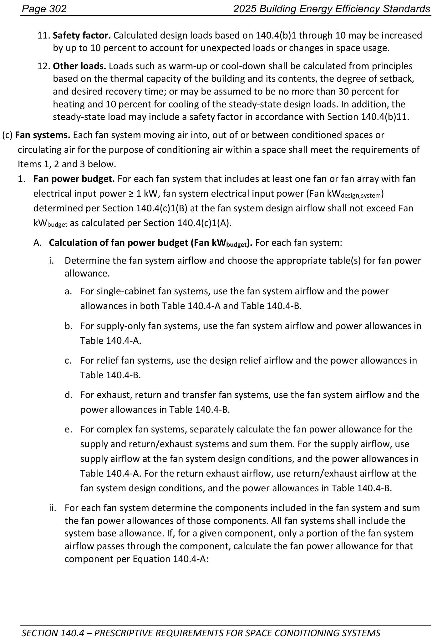
Equation text: Qsys = The fan system airflow in cfm
Needs visual review