Text in this table
SECTION 120.3 – REQUIREMENTS FOR PIPE INSULATION Nonresidential and hotel/motel buildings shall comply with the applicable requirements of Sections 120.3(a) through 120.3(c). (a) General requirements. The piping conditions listed below for space-conditioning, service water-heating, and process heating and process cooling systems piping with fluid normal operating temperatures listed in Table 120.3-A-1 or Table 120.3-A-2, and the fluid distribution system shall have at least the amount of insulation specified in Subsection (c): 1. Space cooling systems. All refrigerant suction, chilled water, and brine fluid distribution systems. 2. Space heating systems. All refrigerant suction, steam, steam condensate and hot water fluid distribution systems. 3. Service water-heating systems. A. Recirculating system piping, including the supply and return piping to the water heater. B. The first 8 feet of hot and cold outlet piping, including piping between a storage tank and a heat trap, for a nonrecirculating storage system. C. Pipes that are externally heated. 4. Process heating system piping. All refrigerant, steam, steam condensate and hot water fluid distribution systems for heating a process unrelated to space conditioning or service water-heating. 5. Process cooling system piping. All refrigerant suction, chilled water, and brine fluid distribution systems for cooling a process unrelated to space conditioning. Insulation conductivity shall be determined in accordance with ASTM C335 at the mean temperature listed in Table 120.3-A-1 or Table 120.3-A-2, and shall be rounded to the nearest 1/100 Btu-inch per hour per square foot per °F. Fluid distribution systems include all elements that are in series with the fluid flow, such as pipes, fittings, pumps, valves, strainers, coil u-bends, and air separators, but not including elements that are not in series with the fluid flow, such as expansion tanks, fill lines, chemical feeders, and drains. Exception to Section 120.3(a)2: Heat pump refrigerant vapor line shall be installed with a minimum of 0.5 inch thick or R-3.0 insulation for nonresidential buildings and 0.75 inch thick or R-6.0 insulation for residential buildings. No insulation is required on the refrigerant liquid line. (b) Insulation protection. Pipe insulation shall be protected from damage due to sunlight, moisture, equipment maintenance and wind. Protection shall, at minimum, include the following: 1. Pipe insulation exposed to weather shall be protected by a cover suitable for outdoor service. The cover shall be water retardant and provides shielding from solar radiation that can cause degradation of the material. Adhesive tape shall not be used to provide this protection. 2. Pipe insulation covering chilled water piping and refrigerant suction piping located outside the conditioned space shall include, or be protected by, a Class I or Class II vapor retarder. All penetrations and joints shall be sealed. 3. Pipe insulation buried below grade must be installed in a water proof and non-crushable casing or sleeve. (c) Insulation thickness 1. For insulation with a conductivity in the range shown in Table 120.3-A-1 or Table 120.3-A-2 for the applicable fluid temperature range, the insulation shall have the applicable minimum thickness or R-value shown in Table 120.3-A-1 or Table 120.3-A-2. 2. For insulation with a conductivity outside the range shown in Table 120.3-A-1 or Table 120.3-A2 for the applicable fluid temperature range, the insulation shall have a minimum R-value shown in Table 120.3-A-1 or Table 120.3-A-2 or thickness as calculated:
| Fluid Operating Temperature Range (°F) | Insulation Conductivity ( Btu·in/h·ft2· °F) | Insulation Mean Rating Temperature (°F) | Nominal Pipe Diameter < 1 inch | Nominal Pipe Diameter 1 to < 1.5 inches | Nominal Pipe Diameter 1.5 to < 4 inches | Nominal Pipe Diameter 4 to < 8 inches | Nominal Pipe Diameter 8 inches and larger |
|---|---|---|---|---|---|---|---|
| Below 40 | 0.20-0.26 | 50 | 1.0 inch | 1.5 inches | 1.5 inches | 1.5 inches | 1.5 inches |
| Below 40 | 0.20-0.26 | 50 | R-8.5 | R-14 | R-12 | R-10 | R-9 |
Text in this figure
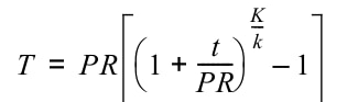
T PR 1 t PR ------- +
K
k---
1 – =
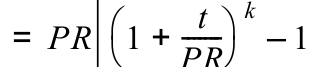
Equation text: 1 – =
Needs visual review

Equation text: T = insulation thickness for material with conductivity K, inches.
Needs visual review

Equation text: t = Insulation thickness from Table 120.3-A-1 or Table 120.3-A-2, inches.
Needs visual review
| Fluid Operating Temperature Range (°F) | Insulation Conductivity (Btu·in/h·ft2· °F) | Insulation Mean Rating Temperature (°F) | Nominal Pipe Diameter < 1 inch | Nominal Pipe Diameter 1 to < 1.5 inches | Nominal Pipe Diameter 1.5 to < 4 inches | Nominal Pipe Diameter 4 to < 8 inches | Nominal Pipe Diameter 8 inches and larger |
|---|---|---|---|---|---|---|---|
| Above 350 | 0.32-0.34 | 250 | 4.5 inches | 5.0 inches | 5.0 inches | 5.0 inches | 5.0 inches |
| Above 350 | 0.32-0.34 | 250 | R-37 | R-41 | R-37 | R-27 | R-23 |
| 251-350 | 0.29-0.32 | 200 | 3.0 inches | 4.0 inches | 4.5 inches | 4.5 inches | 4.5 inches |
| 251-350 | 0.29-0.32 | 200 | R-24 | R-34 | R-35 | R-26 | R-22 |
| 201-250 | 0.27-0.30 | 150 | 2.5 inches | 2.5 inches | 2.5 inches | 3.0 inches | 3.0 inches |
| 201-250 | 0.27-0.30 | 150 | R-21 | R-20 | R-17.5 | R-17 | R-14.5 |
| 141-200 | 0.25-0.29 | 125 | 1.5 inches | 1.5 inches | 2.0 inches | 2.0 inches | 2.0 inches |
| 141-200 | 0.25-0.29 | 125 | R-11.5 | R-11 | R-14 | R-11 | R-10 |
| 105-140 | 0.22-0.28 | 100 | 1.0 inch | 1.5 inches | 1.5 inches | 1.5 inches | 1.5 inches |
| 105-140 | 0.22-0.28 | 100 | R-7.7 | R-12.5 | R-11 | R-9 | R-8 |
| Fluid Operating Temperature Range (°F) | Insulation Conductivity ( Btu·in/h·ft2· °F) | Insulation Mean Rating Temperature (°F) | Nominal Pipe Diameter < 1 inch | Nominal Pipe Diameter 1 to < 1.5 inches | Nominal Pipe Diameter 1.5 to < 4 inches | Nominal Pipe Diameter 4 to < 8 inches | Nominal Pipe Diameter 8 inches and larger |
|---|---|---|---|---|---|---|---|
| Residential 40-60 | 0.21-0.27 | 75 | 0.75 inch | 0.75 inch | 1.0 inch | 1.0 inch | 1.0 inch |
| Residential 40-60 | 0.21-0.27 | 75 | R-6 | R-5 | R-7 | R-6 | R-5 |
| Nonresidential 40-60 | 0.21-0.27 | 75 | 0.5 inch | 0.5 inch | 1.0 inch | 1.0 inch | 1.0 inch |
| Nonresidential 40-60 | 0.21-0.27 | 75 | R-3 | R-3 | R-7 | R-6 | R-5 |