p.169Control requirements for heat pumps with supplementary heaters in single-family residential buildings are specified in Section 150.0(h)7 and Section 150.0(i)2. Heat pumps with supplementary heaters in nonresidential and multifamily buildings shall have controls:
p.170G. 225 divided by the sulfates of the entering make-up water
p.172CONTINUED: TABLE 110.2-A AIR CONDITIONERS AND CONDENSING UNITS – MINIMUM EFFICIENCY REQUIREMENTS
p.173TABLE 110.2-B HEAT PUMPS – MINIMUM EFFICIENCY REQUIREMENTS
p.174CONTINUED: TABLE 110.2-B HEAT PUMPS – MINIMUM EFFICIENCY REQUIREMENTS (continued)
p.177CONTINUED: TABLE 110.2-D WATER CHILLING PACKAGES – MINIMUM EFFICIENCY REQUIREMENTS a,b
p.179CONTINUED: TABLE 110.2-E PERFORMANCE REQUIREMENTS FOR HEAT REJECTION EQUIPMENT
p.172(continued)
| Equipment Type | Size Category | Path A Efficiency a,b | Path B Efficiency a,b | Test Procedure c |
|---|---|---|---|---|
| Air Cooled, With Condenser Electrically Operated | < 150 Tons | ≥ 10.100 EER ≥ 13.700 IPLV | ≥ 9.700 EER ≥15.800 IPLV | AHRI 550/590 |
| Air Cooled, With Condenser Electrically Operated | ≥ 150 Tons | ≥ 10.100 EER ≥ 14.000 IPLV | ≥ 9.700 EER ≥16.100 IPLV | AHRI 550/590 |
| Air Cooled, Without Condenser Electrically Operated | All Capacities | Air-cooled chillers without condensers must be rated with matching condensers and comply with the air- cooled chiller efficiency requirements. | Air-cooled chillers without condensers must be rated with matching condensers and comply with the air-cooled chiller efficiency requirements. | AHRI 550/590 |
| Water Cooled, Electrically Operated, Reciprocating | All Capacities | Reciprocating units must comply with the water- cooled positive displacement efficiency requirements. | Reciprocating units must comply with the water-cooled positive displacement efficiency requirements. | AHRI 550/590 |
| Water Cooled, Electrically Operated Positive Displacement | < 75 Tons | ≤0.750kW/ton ≤ 0.600 IPLV | ≤ 0.780 kW/ton ≤ 0.500 IPLV | AHRI 550/590 |
| Water Cooled, Electrically Operated Positive Displacement | ≥ 75 tons and < 150 tons | ≤ 0.720 kW/ton ≤ 0.560 IPLV | ≤ 0.750 kW/ton ≤ 0.490 IPLV | AHRI 550/590 |
| Water Cooled, Electrically Operated Positive Displacement | ≥ 150 tons and < 300 tons | ≤ 0.660 kW/ton ≤ 0.540 IPLV | ≤ 0.680 kW/ton ≤ 0.440 IPLV | AHRI 550/590 |
| Water Cooled, Electrically Operated Positive Displacement, | ≥ 300 Tons and < 600 tons | ≤ 0.610kW/ton ≤ 0.520 IPLV | ≤ 0.625 kW/ton ≤ 0.410 IPLV | AHRI 550/590 |
| Water Cooled, Electrically Operated Positive Displacement | ≥ 600 tons | ≤ 0.560 kW/ton ≤ 0.500 IPLV | ≤ 0.585 kW/ton ≤ 0.380 IPLV | AHRI 550/590 |
| Equipment Type | Size Category | Path A Efficiency a,b | Path B Efficiency a,b | Test Procedure c |
| Water Cooled, Electrically Operated, Centrifugal | < 150 Tons | ≤ 0.610 kW/ton ≤ 0.550IPLV | ≤ 0.695 kW/ton ≤ 0.440 IPLV | AHRI 550/590 |
| Water Cooled, Electrically Operated, Centrifugal | ≥ 150 tons and < 300 tons | ≤ 0.610 kW/ton ≤ 0.550 IPLV | ≤ 0.635 kW/ton ≤ 0.400 IPLV | AHRI 550/590 |
| Water Cooled, Electrically Operated, Centrifugal | ≥ 300 tons and < 400 tons | ≤ 0.560 kW/ton ≤ 0.520 IPLV | ≤ 0.595 kW/ton ≤ 0.390 IPLV | AHRI 550/590 |
| Water Cooled, Electrically Operated, Centrifugal | ≥ 400 tons and < 600 tons | ≤ 0.560 kW/ton ≤ 0.500 IPLV | ≤ 0.585 kW/ton ≤ 0.380 IPLV | AHRI 550/590 |
| Water Cooled, Electrically Operated, Centrifugal | ≥ 600 tons | ≤ 0.560 kW/ton ≤ 0.500 IPLV | ≤ 0.585 kW/ton ≤ 0.380 IPLV | AHRI 550/590 |
| Air Cooled Absorption, Single Effect | All Capacities | ≥0.600 COP | N.A. d | AHRI 560 |
| Water Cooled Absorption, Single Effect | All Capacities | ≥ 0.700 COP | N.A. d | AHRI 560 |
| Absorption Double Effect, Indirect-Fired | All Capacities | ≥ 1.000 COP ≥ 1.050 IPLV | N.A. d | AHRI 560 |
| Absorption Double Effect, Direct-Fired | All Capacities | ≥ 1.000 COP ≥1.000 IPLV | N.A. d | AHRI 560 |
| Water Cooled Gas Engine Driven Chiller | All Capacities | ≥ 1.2 COP ≥ 2.0 IPLV | N.A. d | ANSI Z21.40.4A |
| Equipment Type | Total System Heat Rejection Capacity at Rated Conditions | Subcategory or Rating Condition | Performance Required ,a ,b, c, d | Test Procedure e |
|---|---|---|---|---|
| Propeller or axial fan Open-circuit cooling towers | All | 95°F entering water 85°F leaving water 75°F entering air wb | ≥ 42.1 gpm/hp | CTI ATC-105 and CTI STD-201 RS |
| Centrifugal fan Open-circuit cooling towers | All | 95°F entering water 85°F leaving water 75°F entering air wb | ≥ 20.0 gpm/hp | CTI ATC-105 and CTI STD-201 RS |
| Propeller or axial fan closed-circuit cooling towers | All | 102°F entering water 90°F leaving water 75°F entering air wb | ≥ 16.1 gpm/hp | CTI ATC-105S and CTI STD-201 RS |
| Centrifugal fan closed-circuit cooling towers | All | 102°F entering water 90°F leaving water 75°F entering air wb | ≥ 7.0 gpm/hp | CTI ATC-105S and CTI STD-201 RS |
| Propeller or axial fan evaporative condensers | All | R-448A test fluid 165⁰F entering gas temp 105⁰F condensing temp 75⁰F entering air wb | ≥ 157,000 Btu/h • hp | CTI ATC-106 |
| Propeller or axial fan evaporative condensers | All | Ammonia test fluid 140⁰F entering gas temp 96.3⁰F condensing temp 75⁰F entering air wb | ≥ 134,000 Btu/h • hp | CTI ATC-106 |
| Centrifugal fan evaporative condensers | All | R-448A test fluid 165⁰F entering gas temp 105⁰F condensing temp 75⁰F entering air wb | ≥ 135,000 Btu/h • hp | CTI ATC-106 |
| Equipment Type | Total System Heat Rejection Capacity at Rated Conditions | Subcategory or Rating Condition | Performance Required ,a ,b, c, d | Test Procedure e |
| Centrifugal fan evaporative condensers | All | Ammonia test fluid 140⁰F entering gas temp 96.3⁰F condensing temp 75⁰F entering air wb | ≥ 110,000 Btu/h • hp | CTI ATC-106 |
| Air cooled condensers | All | 125°F condensing temperature 190°F entering gas temperature 15°F subcooling 95°F entering drybulb | ≥ 176,000 Btu/h · hp | AHRI 460 |
| Propeller or axial fan dry coolers (air- cooled fluid coolers) | All | 115°F entering water 105°F leaving water 95°F entering air db | > 4.5 gpm/hp | CTI ATC-105DS |
| Equipment Type | Size Category | Rating Condition | Efficiency a | Test Procedureb |
|---|---|---|---|---|
| Air Cooled (Cooling Mode), both split system and single package | ≥ 65,000 Btu/h and < 135,000 Btu/h | 11.0 EER Federal Minimum IEER | AHRI 340/360 | |
| Air Cooled (Cooling Mode), both split system and single package | ≥ 135,000 Btu/h and < 240,000 Btu/h | 10.6 EER Federal Minimum IEER | AHRI 340/360 | |
| Air Cooled (Cooling Mode), both split system and single package | ≥ 240,000 Btu/h | 9.5 EER Federal Minimum IEER | AHRI 340/360 | |
| Water source (cooling mode) | ≥ 65,000 Btu/h and < 135,000 Btu/h | 86ºF entering water | Federal Minimum EER | ISO-13256-1 |
| Groundwater source (cooling mode) | < 135,000 Btu/h | 59ºF entering water | 18.0 EER | ISO-13256-1 |
| Ground source (cooling mode) | < 135,000 Btu/h | 77ºF entering water | 14.1 EER | ISO-13256-1 |
| Water source water-to-water (cooling mode) | < 135,000 Btu/h | 86ºF entering water | 10.6 EER | ISO-13256-2 |
| Groundwater source water-to- water (cooling mode) | < 135,000 Btu/h | 59ºF entering water | 16.3 EER | ISO-13256-2 |
| Ground source brine-to-water (cooling mode) | < 135,000 Btu/h | 77ºF entering water | 12.1 EER | ISO-13256-2 |
| Air Cooled (Heating Mode) Split system and single package | ≥ 65,000 Btu/h and < 135,000 Btu/h (cooling capacity) | 47° F db/43° F wb outdoor air | Federal Minimum COP | AHRI 340/360 |
| Air Cooled (Heating Mode) Split system and single package | ≥ 65,000 Btu/h and < 135,000 Btu/h (cooling capacity) | 17° F db/15° F wb outdoor air | 2.25 COP | AHRI 340/360 |
| Equipment Type | Size Category | Rating Condition | Efficiency a | Test Procedureb |
| Air Cooled (Heating Mode) Split system and single package | ≥ 135,000 Btu/h and < 240,000 Btu/h (cooling capacity) | 47° F db/43° F wb outdoor air | Federal Minimum COP | AHRI 340/360 |
| Air Cooled (Heating Mode) Split system and single package | ≥ 240,000 Btu/h and < 760,000 Btu/h | 47° F db/43° F wb outdoor air | Federal Minimum COP | AHRI 340/360 |
| Air Cooled (Heating Mode) Split system and single package | ≥ 135,000 Btu/h (cooling capacity) | 17° F db/15° F wb outdoor air | 2.05 COP | AHRI 340/360 |
| Water source (heating mode) | < 135,000 Btu/h (cooling capacity) | 68ºF entering water | Federal Minimum COP | ISO-13256-1 |
| Water source (heating mode) | ≥ 135,000 Btu/h and < 240,000 Btu/h | 68ºF entering water | Federal Minimum COP | ISO-13256-1 |
| Groundwater source (heating mode) | < 135,000 Btu/h (cooling capacity) | 50ºF entering water | 3.7 COP | ISO-13256-1 |
| Ground source (heating mode) | < 135,000 Btu/h (cooling capacity) | 32ºF entering water | 3.2 COP | ISO-13256-1 |
| Water source water-to-water (heating mode) | < 135,000 Btu/h (cooling capacity) | 68ºF entering water | 3.7 COP | ISO-13256-2 |
| Groundwater source water-to- water (heating mode) | < 135,000 Btu/h (cooling capacity) | 50ºF entering water | 3.1 COP | ISO-13256-2 |
| Ground source brine-to-water (heating mode) | < 135,000 Btu/h (cooling capacity) | 32ºF entering water | 2.5 COP | ISO-13256-2 |
| Equipment Type | Size Category | Subcategory or Rating Condition | Efficiency | Test Procedurea |
|---|---|---|---|---|
| Air-Cooled Gas- Engine Heat Pump (Cooling Mode) | All Capacities | 95° F db Outdoor Air | 0.60 COP | ANSI Z21.40.4A |
| Air-Cooled Gas- Engine Heat Pump (Heating Mode) | All Capacities | 47° F db/43° F wb Outdoor Air | 0.72 COP | ANSI Z21.40.4A |
p.170135 divided by the silica of the entering make-up water
| Equipment Type | Size Category | Efficiency | Test Procedureb |
|---|---|---|---|
| Air conditioners, air cooled both split system and single package | ≥ 65,000 Btu/h and < 135,000 Btu/h | 11.2 EERa Federal Minimum IEERa | AHRI 340/360 |
| Air conditioners, air cooled both split system and single package | ≥ 135,000 Btu/h and < 240,000 Btu/h | 11.0 EERa Federal Minimum IEERa | AHRI 340/360 |
| Air conditioners, air cooled both split system and single package | ≥ 240,000 Btu/h and < 760,000 Btu/h | 10.0 EERa Federal Minimum IEERa | AHRI 340/360 |
| Air conditioners, air cooled both split system and single package | ≥ 760,000 Btu/h | 9.7 EERa 12.5 IEERa | AHRI 340/360 |
| Air conditioners, water cooled | ≥ 65,000 Btu/h and < 135,000 Btu/h | Federal Minimum EERa 13.9 IEERa | AHRI 340/360 |
| Air conditioners, water cooled | ≥135,000 Btu/h and < 240,000 Btu/h | Federal Minimum EERa 13.9 IEERa | AHRI 340/360 |
| Air conditioners, water cooled | ≥240,000 Btu/h and < 760,000 Btu/h | Federal Minimum EERa 13.6 IEERa | AHRI 340/360 |
| Equipment Type | Size Category | Efficiency | Test Procedureb |
| Air conditioners, water cooled | ≥ 760,000 Btu/h | 12.2EERa 13.5 IEERa | AHRI 340/360 |
| Air conditioners, evaporatively cooled | ≥65,000 Btu/h and < 135,000 Btu/h | Federal Minimum EERa 12.3 IEERa | AHRI 340/360 |
| Air conditioners, evaporatively cooled | ≥ 135,000 Btu/h and < 240,000 Btu/h | Federal Minimum EERa 12.2 IEERa | AHRI 340/360 |
| Air conditioners, evaporatively cooled | ≥240,000 Btu/h and < 760,000 Btu/h | Federal Minimum EERa 12.1 IEERa | AHRI 340/360 |
| Air conditioners, evaporatively cooled | ≥ 760,000 Btu/h | 11.7 EERa 11.9 IEERa | AHRI 340/360 |
| Condensing units, air cooled | ≥ 135,000 Btu/h | 10.5 EER Federal Minimum IEER | AHRI 365 |
| Condensing units, water cooled | ≥ 135,000 Btu/h | 13.5 EER Federal Minimum IEER | AHRI 365 |
| Condensing units, evaporatively cooled | ≥ 135,000 Btu/h | 13.5 EER Federal Minimum IEER | AHRI 365 |
p.170I. Langelier Saturation Index =
p.168SECTION 110.2 – MANDATORY REQUIREMENTS FOR SPACE-CONDITIONING

p.175Engine Heat Pump
p.169In which the cut-on temperature for heat pump heating is higher than the cut-on temperature for supplementary heating, and the cut-off temperature for heat pump heating is higher than the cut-off temperature for supplementary heating.
p.168Certification by manufacturers. Any space-conditioning equipment listed in this section may be installed only if the manufacturer has certified to the Commission that the equipment complies with all the applicable requirements of this section.
p.170C = Conductivity of the entering make-up water.
p.170H = Calcium hardness of the entering make-up water.
p.175Engine Heat Pump
p.168(a) Efficiency. Equipment shall meet the applicable efficiency requirements in Tables 110.2-A through 110.2-L, subject to
p.170M = M-alkalinity excluding galvanized steel of the entering make-up water.
p.168the following:
p.169A. Defrost; and
p.170T = Max skin temperature
p.168If more than one efficiency standard is listed for any equipment in Tables 110.2-A through 110.2-L, the equipment shall meet all the applicable standards that are listed; and
p.169B. Transient periods such as start-ups and following room thermostat setpoint advance, if the controls provide
p.175a Applicable test procedure and reference year are provided under the definitions.p.176
p.170Cooling towers shall not allow blowdown until one or more of the parameters in Table 110.2-A-1 reaches the maximum value specified:
p.169preferential rate control, intelligent recovery, staging, ramping or another control mechanism designed to preclude the unnecessary operation of supplementary heating.
p.168If more than one test method is listed in Tables 110.2-A through 110.2-L, the equipment shall comply with the applicable efficiency standard when tested with each listed test method; and
p.168Where equipment serves more than one function, it shall comply with the efficiency standards applicable to each function; and
| Recirculating Water Parameters | Maximum Values |
|---|---|
| Conductivity (micro-siemens/cm) | 2,970 micro-siemens/cm |
| Total dissolved solids (ppm) | 1,845 ppm |
| Total alkalinity as CaCO3 (ppm) excluding galvanized steel | 540 ppm |
| Total alkalinity as CaCO3 (ppm) galvanized steel (passivated) | 450 ppm |
| Calcium hardness as CACO3 (ppm) | 540 ppm |
| Chlorides as Cl (ppm) | 270 ppm |
| Sulfates (ppm) | 225 ppm |
| Silica (ppm) | 135 ppm |
| Langelier saturation index (LSI) | 2.5 (LSI) |
p.169(c) Thermostats. All heating or cooling systems not controlled by a central energy management control system (EMCS)
p.169shall have a setback thermostat.
p.168Where a requirement is for equipment rated at its “maximum rated capacity” or “minimum rated capacity,” the capacity shall be as provided for and allowed by the controls, during steady-state operation.
p.169Setback capabilities. All thermostats shall have a clock mechanism that allows the building occupant to program the temperature setpoints for at least four periods within 24 hours. Thermostats for heat pumps shall meet the requirements of Section 110.2(b).
p.179a For purposes of this table, open-circuit cooling tower performance is defined as the water flow rating of the tower at
p.179the given rated conditions divided by the fan motor nameplate power.
p.179b For purposes of this table, closed-circuit cooling tower performance is defined as the process water flow rating of the
p.179tower at the given rated conditions divided by the sum of the fan motor nameplate rated power and the integral spray pump motor nameplate power.
p.168Adjusted maximum full-load kW/ton rating = (full- load kW/ton from Table 110.2-D)/Kadj
p.169(d) Gas-fired and oil-fired furnace standby loss controls. Gas-fired and oil-fired forced-air furnaces with input ratings ≥
p.169225,000 Btu/hr shall also have an intermittent ignition or interrupted device (IID), and have either power venting or a flue damper. A vent damper is an acceptable alternative to a flue damper for furnaces where combustion air is drawn from the conditioned space. All furnaces with input ratings ≥ 225,000 Btu/hr, including electric furnaces, that are not located within the conditioned space shall have jacket losses not exceeding 0.75 percent of the input rating.
p.179c For purposes of this table dry cooler performance is defined as the process water flow rating of the unit at the given
p.168Adjusted maximum NPLV rating = (IPLV from Table 110.2-D)/Kadj
p.179thermal rating condition divided by the total fan motor nameplate power of the unit and air-cooled condenser performance is defined as the heat rejected from the refrigerant divided by the fan motor nameplate power of the unit.
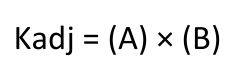
Equation text: Kadj = (A) × (B)
Needs visual review
p.179d Open cooling towers shall be tested using the test procedures in CTI ATC-105. Performance of factory assembled open
p.169(e) Open and closed-circuit cooling towers. All open and closed-circuit cooling tower installations shall comply with the
p.170Be equipped with a flow meter with an analog output for flow either hardwired or available through a gateway on the makeup water line.
p.172Deduct 0.2 from the required EERs and IEERs for units with a heating section other than electric resistance heat. Applicable test procedure and reference year are provided under the definitions.p.173
p.168A = 0.00000014592 × (LIFT)4 – 0.0000346496 × (LIFT)3 + 0.00314196 × (LIFT)2 – 0.147199 × (LIFT) + 3.9302
p.179cooling towers shall be either certified as base models as specified in CTI STD-201 or verified by testing in the field by a CTI approved testing agency. Open factory assembled cooling towers with custom options added to a CTI certified base model for the purpose of safe maintenance or to reduce environmental or noise impact shall be rated at 90 percent of the CTI certified performance of the associated base model or at the manufacturer’s stated performance, whichever is less. Base models of open factory assembled cooling towers are open cooling towers configured in exact accordance with the Data of Record submitted to CTI as specified by CTI STD-201. There are no certification requirements for field erected cooling towers.
p.169following:
p.168LIFT = LvgCond – LvgEvap (°F)
p.169Be equipped with conductivity controls that maximize cycles of concentration based on local water quality conditions. Controls shall automate system bleed and chemical feed based on conductivity. Conductivity controllers shall be installed in accordance with manufacturer’s specifications in order to maximize accuracy.
p.170Be equipped with an overflow alarm to prevent overflow of the sump in case of makeup water valve failure. Overflow alarm shall send an audible signal or provide an alert via the energy management control system to the tower operator in case of sump overflow.
p.177a. No requirements for:
p.168LvgCond = Full-load leaving condenser fluid temperature (°F)
p.1771. Centrifugal chillers with design leaving evaporator temperature < 36°F; or 2. Positive displacement chillers with design leaving fluid temperature ≤ 32°F; or 3. Absorption chillers with design leaving fluid temperature < 40°F. b. Must meet the minimum requirements of Path A or Path B. However, both the full load (COP) and IPLV must be
p.168LvgEvap = Full-load leaving evaporator fluid temperature (°F)
p.169Documentation of maximum achievable cycles of concentration. Building owners shall document the cycles of concentration achievable based on local water supply conditions as reported annually by the local water supplier, and using the calculations below. The calculations are intended to determine maximum achievable cycles of concentration based on the parameters identified in Table 110.2-A-1. Building owner shall document maximum achievable cycles of concentration on the mechanical compliance form which shall be reviewed and signed by the Professional Engineer (P.E.) of Record.
p.170Be equipped with efficient drift eliminators that achieve drift reduction to 0.002 percent of the circulated water volume for counter-flow towers and 0.005 percent for cross-flow towers.

Equation text: B = (0.0015 × LvgEvap) + 0.934
Needs visual review
p.168The adjusted full-load and NPLV values are only applicable for centrifugal chillers meeting all of the following full-load design ranges:
p.177met to fulfill the requirements of the applicable Path. See Section 100.1 for definitions. d. N.A. means not applicable.p.178
p.179e Applicable test procedure and reference year are provided under the definitions. For refrigerated warehouses or
p.170Conductivity controls and overflow alarm shall be verified according to NA 7.5.18.
p.179commercial refrigeration applications, condensers shall comply with requirements specified by Section 120.6(a) or Section 120.6(b).
p.168• Minimum Leaving Evaporator Fluid Temperature: 36°F
p.168• Maximum Leaving Condenser Fluid Temperature: 115°F
p.170(f) Low leakage air-handling units. To qualify as a low leakage air-handling unit for use for meeting the requirements for
p.169The maximum achievable cycles of concentrations are based on the local water supply quality as reported by the local water supplier, and shall be the minimum of:
p.174a Deduct 0.2 from the required EERs and IEERs for units with a heating section other than electric resistance heat. b Applicable test procedure and reference year are provided under the definitions.p.175
p.168• LIFT ≥ 20°F and ≤ 80°F
p.170applicable low leakage air-handling unit compliance credit(s) available in the performance standards set forth in Sections 150.1(b) and 140.1, the manufacturer shall certify to the Energy Commission that the air-handling unit meets the specifications in Reference Joint Appendix JA9.p.171
p.168Centrifugal chillers designed to operate outside of these ranges are not covered by this exception.
p.169A. 2970 divided by the conductivity of the entering make-up water
p.169B. 1845 divided by the total dissolved solids of the entering make-up water
p.169C. 540 divided by the M-alkalinity excluding galvanized steel of the entering make-up water
p.169D. 450 divided by the M-alkalinity including galvanized steel of the entering make-up water
p.169E. 540 divided by the calcium hardness of the entering make-up water
p.168(b) Controls for heat pumps with supplementary heaters.p.169
p.169F. 270 divided by the chlorides of the entering make-up waterp.170
p.168SECTION 110.2 – MANDATORY REQUIREMENTS FOR SPACE-CONDITIONING EQUIPMENT
p.169SECTION 110.2 – MANDATORY REQUIREMENTS FOR SPACE-CONDITIONING EQUIPMENT
p.170SECTION 110.2 – MANDATORY REQUIREMENTS FOR SPACE-CONDITIONING EQUIPMENT
p.171SECTION 110.2 – MANDATORY REQUIREMENTS FOR SPACE-CONDITIONING EQUIPMENT
p.172SECTION 110.2 – MANDATORY REQUIREMENTS FOR SPACE-CONDITIONING EQUIPMENT
p.173SECTION 110.2 – MANDATORY REQUIREMENTS FOR SPACE-CONDITIONING EQUIPMENT
p.174SECTION 110.2 – MANDATORY REQUIREMENTS FOR SPACE-CONDITIONING EQUIPMENT
p.175SECTION 110.2 – MANDATORY REQUIREMENTS FOR SPACE-CONDITIONING EQUIPMENT
p.176SECTION 110.2 – MANDATORY REQUIREMENTS FOR SPACE-CONDITIONING EQUIPMENT
p.177SECTION 110.2 – MANDATORY REQUIREMENTS FOR SPACE-CONDITIONING EQUIPMENT
p.178SECTION 110.2 – MANDATORY REQUIREMENTS FOR SPACE-CONDITIONING EQUIPMENT
p.179SECTION 110.2 – MANDATORY REQUIREMENTS FOR SPACE-CONDITIONING EQUIPMENT