Text in this table
SECTION 170.2 – PRESCRIPTIVE APPROACH II. System airflow rate in accordance with Subsection A or B below shall be confirmed through field verification and diagnostic testing in accordance with all applicable procedures specified in Reference Residential Appendix Section RA3.3 or an approved alternative procedure as specified by RA1; and A. For small duct high velocity systems, the system airflow rate shall be greater than or equal to 250 cfm per ton; or B. For all other air-cooled air conditioner or air-source heat pump systems, the system airflow rate shall be greater than or equal to 350 cfm per ton. III. The installer shall charge the system according to manufacturer’s specifications. Refrigerant charge shall be verified according to one of the following options, as applicable: A. The installer and rater shall perform the standard charge procedure as specified by Reference Residential Appendix Section RA3.2.2 or an approved alternative procedure as specified by RA1; or B. The installer shall perform the weigh-in charging procedure as specified by Reference Residential Appendix Section RA3.2.3.1, provided the system is of a type that can be verified using the RA3.2.2 standard charge verification procedure and RA3.3 airflow rate verification procedure or approved alternatives in RA1. The ECC-Rater shall verify the charge using RA3.2.2 and RA3.3 or approved alternatives in RA1. Exception to Section 170.2(c)3BiaI: Systems that cannot conform to the specifications for hole location in Reference Residential Appendix Figure RA3.2-1 shall not be required to provide holes as described in Figure RA3.2-1. Exception to Section 170.2(c)3BiaII: Standard ducted systems without zoning dampers may comply with the minimum airflow rate by meeting the applicable requirements in Table 160.3-A and Table 160.3-B as confirmed by field verification and diagnostic testing in accordance with the procedures in Reference Residential Appendix Sections RA3.1.4.4 and RA3.1.4.5. The design clean-filter pressure drop requirements of Section 160.2(b)1D for the system air filter device(s) shall conform to the requirements given in Table 160.3-A and Table 160.3-B. Exception to Section 170.2(c)3BiaIII: When the outdoor temperature is less than 55 degrees F and the installer utilizes the weigh-in charging procedure in Reference Residential Appendix Section RA3.2.3.1 to verify the refrigerant charge, the installer may elect to utilize the verification procedure in Reference Residential Appendix Section RA3.2.3.2. If the verification procedure in Section RA3.2.3.2 is used for compliance, the system’s thermostat shall conform to the specifications in Section 110.12. Ducted systems shall comply with the minimum system airflow rate requirement in Section 170.2(c)3BiaII. b. For air-cooled air conditioners and air-source heat pumps, including but not limited to ducted split systems, ducted packaged systems, small duct high velocity systems and mini-split systems, which are of a type that cannot comply with the requirements of Section 170.2(c)3Bi:
Text in this table
SECTION 170.2 – PRESCRIPTIVE APPROACH iv. Balanced ventilation systems with heat/energy recovery in climate zones 1, 2, 4, 11-14, and 16. A balanced ventilation system with heat or energy recovery shall be used to meet Section 160.2(b)2Aivb1, and shall meet the applicable requirements of a, or b below: a. In Climate Zones 1, 2, 4, 11-14, and 16, balanced ventilation systems serving individual dwelling units shall: 1. Be an energy recovery ventilator (ERV) or heat recovery ventilator (HRV), 2. Have a minimum sensible recovery efficiency of 67 percent, rated at 32 degrees Fahrenheit (0 degrees Celsius), and 3. Have a fan efficacy less than or equal to 0.6 W per cfm. These measures shall be confirmed through field verification in accordance with the procedures in RA3.7.4.4 for buildings with three habitable stories or less, or the procedures in NA2.2.4.1.5 for buildings with four or more habitable stories. b. In Climate Zones 1, 2, 4, 11-14, and 16, balanced ventilation systems serving multiple dwelling units in buildings with four or more habitable stories shall: 1. Be an ERV or HRV, 2. Have a minimum sensible recovery efficiency or effectiveness of 67 percent, rated at 32 degrees Fahrenheit (0 degrees Celsius), 3. Meet the fan power requirements of Section 170.2(c)4A, and 4. Have recovery bypass or control to directly economize with ventilation air based on outdoor air temperature limits specified in Table 170.2-G. These measures shall be field verified in accordance with NA7.18.4. v. In buildings with three habitable stories or less in Climate Zones 5–10 and Climate Zone 15, when a heat pump space-conditioning system is installed to meet the requirements of Section 170.2(c)3Ai, balanced ventilation systems without an ERV or HRV shall have a fan efficacy less than or equal to 0.4 W/cfm. vi. Dwelling unit ventilation system requirements. All HRV/ERV systems serving individual dwelling units shall have a Fault Indicator Display (FID) that is manufacturer certified in compliance with the requirements in Joint Appendix JA17.4. The FID certification shall be verified by an ECC-Rater. Exception to Section 170.2(c)3B: The field verification and ECC-Provider data registry requirements of Reference Residential Appendix RA2 and RA3 are not required for multifamily dwelling units in buildings four habitable stories and greater. The installer shall certify that diagnostic testing was performed in accordance with the applicable procedures. C. HVAC system bypass ducts. Bypass ducts that deliver conditioned supply air directly to the space-conditioning system return duct airflow shall not be used.
| Component | Multi-Zone VAV Systems ≤5,000 cfm1 | Multi-Zone VAV Systems >5,000 and ≤10,000 cfm1 | Multi-Zone VAV Systems >10,000 cfm1 | All Other Fan Systems ≤5,000 cfm | All Other Fan Systems >5,000 and ≤10,000 cfm | All Other Fan Systems >10,000 cfm |
|---|---|---|---|---|---|---|
| Return or exhaust systems required by code or accreditation standards to be fully ducted, or systems required to maintain air pressure differentials between adjacent rooms | 0.116 | 0.100 | 0.089 | 0.116 | 0.102 | 0.091 |
| Return and/or exhaust airflow control devices required for space pressurization control | 0.116 | 0.100 | 0.089 | 0.116 | 0.102 | 0.091 |
| Laboratory and vivarium exhaust systems in high-rise buildings for vertical duct exceeding 75 ft. Value shown is allowed w/cfm per 0.25 in. wg for each 100 feet exceeding 75 feet. [Calculation required, see note 4] | 0.058 | 0.051 | 0.045 | 0.058 | 0.052 | 0.046 |
| Biosafety cabinet. Value shown is allowed w/cfm per 1.0 in. wg air pressure drop. [Calculation required, see note 4] | 0.231 | 0.198 | 0.177 | 0.232 | 0.202 | 0.179 |
| Exhaust filters, scrubbers, or other exhaust treatment required by code or standard. Value shown is allowed w/cfm per 1.0 in. wg air pressure drop. [Calculation required, see note 4] | 0.231 | 0.198 | 0.177 | 0.232 | 0.202 | 0.179 |
| Sound attenuation section [Fans serving spaces with design background noise goals below NC35.] | 0.035 | 0.030 | 0.027 | 0.035 | 0.031 | 0.028 |
| Component | Multi-Zone VAV Systems ≤5,000 cfm | Multi-Zone VAV Systems >5,000 and ≤10,000 cfm | Multi-Zone VAV Systems >10,000 cfm | All Other Fan Systems ≤5,000 cfm | All Other Fan Systems >5,000 and ≤10,000 cfm | All Other Fan Systems >10,000 cfm |
|---|---|---|---|---|---|---|
| Supply System Base Allowance for AHU Serving Spaces≤ 6 Floors Away. | 0.395 | 0.453 | 0.413 | 0.232 | 0.256 | 0.236 |
| Supply System Base Allowance for AHU Serving Spaces > 6 Floors Away | 0.508 | 0.548 | 0.501 | 0.349 | 0.356 | 0.325 |
| MERV 13 to MERV 16 Filter Upstream of Thermal Conditioning Equipment (two times the clean filter pressure drop)2 | 0.136 | 0.114 | 0.105 | 0.139 | 0.120 | 0.107 |
| MERV 13 to MERV 16 Final Filter Downstream of Thermal Conditioning Equipment. (two times the clean filter pressure drop) 2 | 0.225 | 0.188 | 0.176 | 0.231 | 0.197 | 0.177 |
| Filtration Allowance for > Merv 16 or HEPA Filter (two times the clean filter pressure drop) 2 | 0.335 | 0.280 | 0.265 | 0.342 | 0.292 | 0.264 |
| Central Hydronic Heating Coil Allowance | 0.046 | 0.048 | 0.052 | 0.046 | 0.050 | 0.054 |
| Electric Heat Allowance | 0.046 | 0.038 | 0.035 | 0.046 | 0.040 | 0.036 |
| Component | Multi-Zone VAV Systems ≤5,000 cfm | Multi-Zone VAV Systems >5,000 and ≤10,000 cfm | Multi-Zone VAV Systems >10,000 cfm | All Other Fan Systems ≤5,000 cfm | All Other Fan Systems >5,000 and ≤10,000 cfm | All Other Fan Systems >10,000 cfm |
| Gas Heat Allowance | 0.069 | 0.057 | 0.070 | 0.058 | 0.060 | 0.072 |
| Hydronic/DX Cooling Coil, or Heat Pump Coil (wet) Allowance | 0.135 | 0.114 | 0.105 | 0.139 | 0.120 | 0.107 |
| Solid or Liquid Desiccant System Allowance | 0.157 | 0.132 | 0.123 | 0.163 | 0.139 | 0.124 |
| Reheat Coil for Dehumidification Allowance | 0.045 | 0.038 | 0.035 | 0.046 | 0.040 | 0.036 |
| Allowance for evaporative humidifier/cooler in series with a cooling coil. Value shown is allowed watts/cfm per 1.0 in. wg. Determine pressure loss (in. wg) at 400 fpm or maximum velocity allowed by the manufacturer, whichever is less. [Calculation required, see note 4] | 0.224 | 0.188 | 0.176 | 0.231 | 0.197 | 0.177 |
| Allowance for 100% outdoor air system meeting the requirements of Note 5. | 0.000 | 0.000 | 0.000 | 0.070 | 0.100 | 0.107 |
| Energy Recovery Allowance for 0.50 ≤ ERR <0.55 6 | 0.135 | 0.114 | 0.105 | 0.139 | 0.120 | 0.107 |
| Energy Recovery Allowance for 0.55 ≤ ERR <0.60 6 | 0.160 | 0.134 | 0.124 | 0.165 | 0.141 | 0.126 |
| Energy Recovery Allowance for 0.60 ≤ ERR <0.65 6 | 0.184 | 0.155 | 0.144 | 0.190 | 0.163 | 0.146 |
| Energy Recovery Allowance for 0.65 ≤ ERR <0.70 6 | 0.208 | 0.175 | 0.163 | 0.215 | 0.184 | 0.165 |
| Energy Recovery Allowance for 0.70 ≤ ERR <0.75 6 | 0.232 | 0.196 | 0.183 | 0.240 | 0.205 | 0.184 |
| Energy Recovery Allowance for 0.75 ≤ ERR <0.80 6 | 0.257 | 0.216 | 0.202 | 0.264 | 0.226 | 0.203 |
| Energy Recovery Allowance for ERR ≥ 0.80 6 | 0.281 | 0.236 | 0.222 | 0.289 | 0.247 | 0.222 |
| Coil Runaround Loop | 0.135 | 0.114 | 0.105 | 0.139 | 0.120 | 0.107 |
| Allowance for gas phase filtration required by code or accredited standard. Value shown is allowed w/cfm per 1.0 in. wg air pressure drop. [Calculation required, see note 4] | 0.224 | 0.188 | 0.176 | 0.231 | 0.197 | 0.177 |
| Component | Multi-Zone VAV Systems ≤5,000 cfm | Multi-Zone VAV Systems >5,000 and ≤10,000 cfm | Multi-Zone VAV Systems >10,000 cfm | All Other Fan Systems ≤5,000 cfm | All Other Fan Systems >5,000 and ≤10,000 cfm | All Other Fan Systems >10,000 cfm |
| Economizer Return Damper | 0.045 | 0.038 | 0.035 | 0.046 | 0.040 | 0.036 |
| Air Blender Allowance | 0.045 | 0.038 | 0.035 | 0.046 | 0.040 | 0.036 |
| Allowance for sound attenuation section [fans serving spaces with design background noise goals below NC35]. | 0.034 | 0.029 | 0.026 | 0.035 | 0.030 | 0.027 |
| Deduction for systems that feed a terminal unit with a fan with electrical input power < 1kW. | -0.100 | -0.100 | -0.100 | -0.100 | -0.100 | -0.100 |
| Low-turndown single-zone VAV fan systems meeting the requirements in note 7. | 0.000 | 0.000 | 0.000 | .070 | 0.100 | 0.089 |
| Component | Multi-Zone VAV Systems ≤5,000 cfm1 | Multi-Zone VAV Systems >5,000 and ≤10,000 cfm1 | Multi-Zone VAV Systems >10,000 cfm1 | All Other Fan Systems ≤5,000 cfm | All Other Fan Systems >5,000 and ≤10,000 cfm | All Other Fan Systems >10,000 cfm |
|---|---|---|---|---|---|---|
| Exhaust System Base Allowance | 0.221 | 0.246 | 0.236 | 0.186 | 0.184 | 0.190 |
| Filter (any MERV value)2 | 0.046 | 0.041 | 0.036 | 0.046 | 0.041 | 0.035 |
| Energy Recovery Allowance for 0.50 ≤ ERR <0.55 3 | 0.139 | 0.120 | 0.107 | 0.139 | 0.123 | 0.109 |
| Energy Recovery Allowance for 0.55 ≤ ERR <0.60 3 | 0.165 | 0.142 | 0.126 | 0.165 | 0.144 | 0.128 |
| Energy Recovery Allowance for 0.60 ≤ ERR <0.65 3 | 0.190 | 0.163 | 0.146 | 0.191 | 0.166 | 0.148 |
| Energy Recovery Allowance for 0.65 ≤ ERR <0.70 3 | 0.215 | 0.184 | 0.165 | 0.216 | 0.188 | 0.167 |
| Energy Recovery Allowance for 0.70 ≤ ERR <0.75 3 | 0.240 | 0.206 | 0.184 | 0.241 | 0.209 | 0.186 |
| Energy Recovery Allowance for 0.75 ≤ ERR <0.80 3 | 0.265 | 0.227 | 0.203 | 0.266 | 0.231 | 0.205 |
| Energy Recovery Allowance for ERR ≥ 0.80 3 | 0.289 | 0.248 | 0.222 | 0.291 | 0.252 | 0.225 |
| Coil Runaround Loop | 0.139 | 0.120 | 0.107 | 0.139 | 0.123 | 0.109 |
p.5670.224 0.188 0.176 0.231 0.197 0.177p.568
Text in this figure
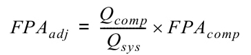
FPAadj
Qcomp
Qsys -------------- FPAcomp × =
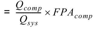
Equation text: Qsys -------------- FPAcomp × =
Needs visual review